

About
Enlighten addresses the disconnect between crash and impact structural optimization and digital validation.
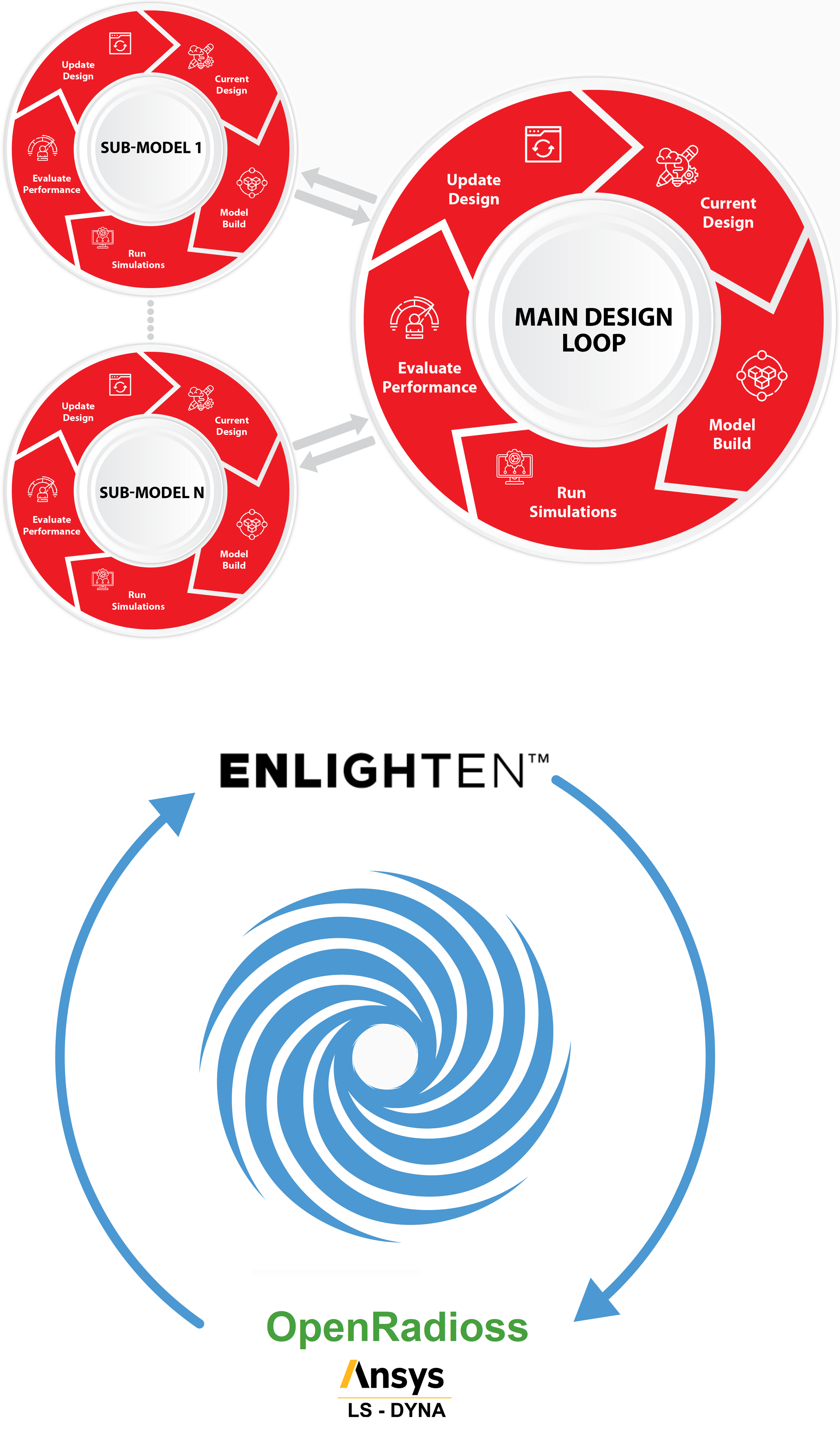
The current typical approach involves using a series of static sub-models to provide design guidance. This guidance is then interpreted into structures, which are then finally assessed within full crash solvers.
This process is time-consuming and often results in designs that either fail to meet performance requirements, or are over-engineered and inefficient.
Enlighten closes this disconnect by iterating directly over crash and impact analyses, utilizing industry-standard full crash solvers such as Ansys LS-Dyna or Altair Radioss/OpenRadioss.
This approach ensures that designs are validated and optimized simultaneously, whilst also eliminating the bottlenecks associated with traditional methods. As a result, designs obtained using Enlighten are:
Holistic, addressing multiple load cases
Pre-validated using industry-standard solvers
Highly optimized and lightweight
Enlighten can be used at any stage in an engineering program, from early concept development to mature design refinement. Its key features include:
Full generative design using a computationally-efficient shell lattice methodology
Part-by-part control over design variables for complex design-for-manufacturing (DfMA) requirements
Developed by a senior CAE crash analyst over a period of six years, Enlighten was created to be used within an industrial setting.
We are currently offering a free trial to a small group of individuals prior to full release. If this is of interest, please register your details below and we will be in touch.
Traditional design process vs Enlighten
Register for Enlighten
Please use the contact form to register your details & we will be in touch.

Generative design

Megacasting

Rocker & crushcan

Warehouse pallet